

Reference Frames#
In orbital mechanics, we track the motion of particles through a Euclidean space. This means we need a frame of reference, also known as a reference frame, in which the motion is tracked. The frame of reference consists of a clock to count time and a non-rotating Cartesian coordinate system to track the \(x\), \(y\), and \(z\) position of the particle. We are going to assume that relativity is not important in this course, so a single universal clock is sufficient to specify the time for all Cartesian coordinate systems.
Types of Reference Frames#
The two types of reference frames are:
Inertial frames
Non-Inertial frames
Profound.
Inertial Reference Frame#
An inertial reference frame is one that is not accelerating. It may be moving at constant velocity, but there can be absolutely no acceleration, including rotation!
Therefore, in an inertial reference frame, an object obeys Newton’s First Law of Motion and its velocity remains constant unless an external force acts on it. Inertial reference frames are always our first choice if possible, because the laws of mechanics tend to take their simplest form in this frame.
In orbital mechanics, we usually define an inertial reference frame with respect to the fixed stars. Of course, the stars are not really fixed—our Sun orbits the center of the galaxy, as do other stars in the Milky Way, and other galaxies may be approaching or receding at some velocity.
However, on the scale of most orbital mechanics problems we have to deal with (on the order of a few days to a few years), assuming the stars are fixed is reasonable.
Non-Inertial Reference Frame#
By contrast to the inertial reference frame, the non-inertial reference frame does accelerate. This gives rise to the so-called fictitious forces, such as the centrifugal force, Coriolis force, and others.
One common example of an accelerating reference frame that you may have seen in Physics is the idea of a ball attached to a string rotating around a point—for instance, spinning a ball on a string above your head. In this case, a reference frame attached to a point which is not spinning would be considered inertial. On the other hand, a reference frame attached to the ball would be rotating and thus accelerating. It would be a non-inertial reference frame (specifically, a rotating reference frame) and would need to include a “fictitious” centrifugal force to satisfy the equations of motion.

Fig. 1 Centripetal force and reaction. Attributed to Richard F. Lyon based on work of en:User:Cburnett, CC BY-SA 4.0, via Wikimedia Commons#
As another example, consider a ball moving on a frictionless, rotating plate. An observer in an inertial frame would see the ball move in a straight line, since the ball does not experience any forces. However, an observer rotating with the frame would see the ball follow a curved path, implying the existence of a force. Since the force is not present in the inertial frame, this is termed a fictitious force.
Fig. 2 Demonstration of the Coriolis force. The observer is shown as the red dot. Attributed to Hubi, CC BY-SA 3.0, via Wikimedia Commons#
Earth Reference Frames#
All reference frames are either inertial or non-inertial, and deciding which type of frame we want to work with is our first choice. The second choice we need to make is where the origin of the frame should be placed.
With respect to the Earth, we will define three separate reference frames:
For now, we will assume that the Earth is a sphere. We use the Earth here since most human spaceflight takes place near the Earth.
Earth-Centered Inertial#
The Earth-Centered Inertial (ECI) frame is an inertial frame with the origin fixed to the center of the Earth, \(C\). This frame uses capital letters for the axes and unit vectors, as shown in Fig. 3.
In the ECI, the \(Z\) axis points towards the North pole and the \(X\)-\(Y\) plane is in the same plane as the equator. Since this is an inertial frame, it is fixed in place with respect to the celestial sphere, the stars surrounding the Earth.
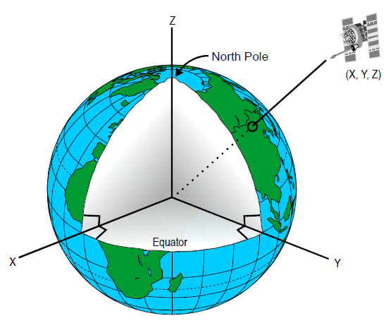
Fig. 3 The Earth Centered Inertial coordinate system has its origin at the center of the Earth and is fixed with respect to the celestial sphere. U.S. Department of Transportation Federal Aviation Administration - Airway Facilities Division, Public domain, via Wikimedia Commons.#
In the ECI, the \(X\) axis points towards the March equinox. The equinoxes are the points in space where the Earth’s equatorial plane and its ecliptic plane intersect. The March equinox occurs when the Sun crosses the equatorial plane from below. This currently happens in the constellation Pisces, although in antiquity this occurred in the constellation Aries (the ram). Thus, the March equinox is also called the First point of Aries.
Earth-Centered, Earth-Fixed#
The Earth-centered, Earth-fixed (ECEF) frame is a non-inertial frame, but with the origin still fixed at the center of the Earth. The main difference from the ECI is that the axes in the ECEF rotate at the same rate as the surface of the Earth.
The ECEF uses lower case, primed letters for the axes and unit vectors. The \(z'\) axis points towards the North pole, and the \(x'\) axis intersects the equator and the prime meridian. Since the ECEF rotates with the Earth, the \(x'\) axis always points through the equator and the prime meridian.

Fig. 4 The Earth-centered, Earth-fixed coordinate system is centered at the center of the Earth and rotates with the same angular velocity, such that the \(x'\) axis always points through the intersection of the prime meridian and the equator.#
Every 24 hours, the ECEF and ECI are aligned. Thus, the angular distance between \(X\) and \(x'\) is \(\theta_G\), and \(\theta_G\) increases at the rate \(\Omega\), the rotation rate of the Earth such that there are 24 hours in the day.

Fig. 5 The angle between the \(X\) axis in the ECI and the \(x'\) axis in the ECEF is \(\theta_G\).#
Topocentric-Horizon#
The final coordinate system determines the position of a particle \(P\) moving arbitrarily above the surface of the Earth. This could be a person, car, airplane, or spacecraft.
The origin, \(O\), of this coordinate system is fixed to the particle. At a given instant, the position of this coordinate system can be determined relative to the ECEF frame by specifying the longitude angle (\(\Lambda\)) and the latitude angle (\(\phi\)), which are positive in the East and North directions respectively. These specify the \(x\) and \(y\) axes of a topocentric-horizon coordinate system, respectively.
The third direction, \(z\), is directly up from the surface of the Earth and is called the zenith. Note that the direction of “up” changes as you move over the surface of the sphere.

Fig. 6 The topocentric-horizon coordinate system is centered at the object. The \(x\) axis points east, the \(y\) axis points north, and the \(z\) axis points up from the Earth. Modified from Original: Brews ohare This Version: CheChe, CC BY-SA 4.0, via Wikimedia Commons#